If a pump shaft breaks, it seems that most pump owners/operators immediately blame the manufacturer. In most cases, however, it is not the manufacturer’s fault. This article looks at the problem and its potential causes. While many of these points are specific to centrifugal pumps, there are also points that apply to all rotating machinery, including turbines, compressors and motors.
Reliable pump manufacturers design pump shafts for normal start-up and operating conditions, but some have higher margins and safety margins for abnormal operating conditions. The main causes of shaft breakage can usually be traced back to operational and system causes.
Fatigue failure, also known as failure due to reverse bending fatigue with rotation, is the most common cause of pump shaft breakage/failure.
Pump shaft design
The role of the shaft is to transfer the rotational motion (speed) and power (torque) from the drive machine to the pump rotor components – primarily the impeller. The basic shaft design uses torque as the main driving force, as torque is the most important design element (speed and power are integral factors of torque).
Pump shaft design also deals with temperature, corrosion, metallurgy, bearing position, bearing fit dimensions, cantilevered components (impellers and couplings), axial and radial forces due to expected hydraulic forces, keyways (keyway size, arrangement and their associated geometry), fillet radii, shaft shoulder fillet, rate of change in diameter and snap ring grooves.
In addition, the axial placement of major rotor components such as impellers and couplings, and the resulting rotor dynamics (e.g. critical speed), are major factors in shaft reliability.
All good initial shaft designs include bending moment diagrams and modal analysis. This paper does not deal with high power multistage pump shafts, where design parameters include whether they are designed for wet or dry operation and the design of rotor stiffness.
When a shaft breaks, many pump users wrongly blame the choice of shaft material, believing they need a stronger shaft. But choosing this “stronger is better” approach often treats the symptoms rather than the root cause. Shaft failure problems may occur less frequently, but the underlying causes are still there.
A small percentage of pump shafts will fail due to metallurgical and manufacturing process problems such as undetected porosity in the base material, improper annealing and/or other process treatments. Some failures are due to improper machining, such as incorrect dimensions, tool resistance, undersized radii, omissions and/or improper grinding and polishing. A small number also fail due to insufficient design margins to withstand torque, fatigue and corrosion.
Another factor that can be attributed to the manufacturer or user is the amount of cantilever in the cantilever pump, referred to as the shaft L/D ratio (expressed as L3/D4, where L is the axial distance from the centre line of the impeller outlet to the centre of the radial bearing and D is the diameter of the shaft). Also known as the “length to diameter ratio” or “shaft stiffness ratio”, it indicates how much the shaft will deflect (bend) due to hydraulic radial forces when the pump is operated away from the design point (optimum efficiency point or BEP).
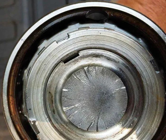
Figure 1: This ANSI pump shaft was incorrectly loaded by the belt and pulley arrangement, resulting in a rotational bending fault. Note the multiple (at least 15) fracture origins at the periphery. The darker area near the middle of the shaft is the instantaneous fast fracture zone (courtesy of the author).
Symptom treatment
A look at the six most commonly used pump shaft materials reveals differences in hardness, strength and corrosion resistance. One point to note is that the Young’s modulus of these materials is almost always in the same range. Young’s modulus is essentially the elasticity of a material – how many times can it be bent before it breaks? More importantly, how far will it bend in each cycle before exceeding the material’s limits?
Young’s modulus should not be confused with strength, toughness or hardness. As the most common shaft materials all have similar Young’s modulus, the decision to change materials is rarely the only solution to correct the root cause of a shaft failure. By addressing other operational factors, the end user will experience greater reliability.
The most common cause of shaft fracture is (rotational) tensile bending fatigue. These fracture types are the result of the bending stresses mentioned earlier. For a given material, the number of cycles and, to some extent, the periodicity (frequency) and distance (strain or amplitude) of the bending cycles will determine how long the shaft will remain as a whole. Failure starts at the weakest point, usually at the radius, fillet, snap ring or keyway. Failures can also occur at the point of bending moment.
For the most common pump shaft materials, fractures caused by bending stresses will occur at right angles (90°) to the shaft centreline, so that these failures look almost as if the shaft has snapped or been severed at that failure point.
A less common failure mode is torsional stress-induced fatigue, where the fracture occurs at an angle of 45° to the shaft centreline. With the advent of variable speed devices, torsional failures are on the increase.
10 possible causes of pump shaft breakage
1) Running away from the BEP: Running away from the pump’s BEP allowable zone is probably the most common cause of shaft failure. Running away from the BEP creates unbalanced hydraulic radial forces. Shaft deflection (deflection) due to radial forces creates a bending force that will occur twice for every revolution of the shaft. For example, a shaft rotating at 3,550 rpm will bend 7,100 times per minute. This bending force generates shaft tensile bending fatigue. Most shafts can handle a high number of cycles if the magnitude of deflection (strain) is low enough.
2) Shaft bending: The problem of shaft bending follows the same logic as the shaft deflection described above. Purchase pumps and spare shafts from manufacturers who have high standards/specifications for shaft straightness. Due diligence would be prudent. Most runout of the pump shaft is required to be controlled within 0.001 to 0.002 inches measured as a Total Indicator Reading (TIR).
3) Impeller or Rotor Unbalance: An unbalanced impeller will produce a “shaft whip” on the shaft during operation. The effect is the same as shaft bending and/or deflection and the shaft will be measured straight even if you stop the pump to check the shaft. It can be argued that impeller balancing is just as important for low speed pumps as it is for high speed pumps. The number of bending cycles is reduced for a given time frame, but the magnitude of the displacement (strain) is kept in the same range as the higher speed due to unbalance.
(4) Fluid properties: Typically, issues relating to fluid properties involve the design of pumps for a (lower) viscosity but subject to higher viscosity fluids. There is a very simple example where for example a pump is selected and designed to pump No. 4 fuel oil at 95 °F and then it is used to pump fuel oil at 35 °F (an approximate difference in viscosity of 235 centipoise). An increase in specific gravity can lead to similar problems. Note also that corrosion can significantly reduce the fatigue strength of shaft materials. In these environments, shafts with high corrosion resistance are a good choice.
5) Variable speed: Torque is inversely proportional to speed. As the pump speed decreases, the shaft torque increases. For example, a 100 hp pump at 875 rpm requires twice as much torque as a 100 hp pump at 1,750 rpm. In addition to the maximum brake horsepower (BHP) limit for the entire shaft, the user must also check the allowable BHP limit per 100 rpm for the pump application.
6) Improper use: Ignoring the manufacturer’s guidelines will lead to problems with the shaft. If the pump is driven by an engine rather than by an electric motor or steam turbine, many pump shafts have a derating factor due to intermittent versus continuous torque. If the pump is not directly driven (via a coupling), such as belt/pulley driven or chain/sprocket driven, the shaft may be significantly derated. Many self-priming trash and slurry pumps are designed to be belt driven and are therefore less of a problem. Pumps manufactured to American National Standards Institute (ANSI) specification B73.1 are not designed to be belt driven (unless an intermediate shaft is used.) ANSI pumps can be belt driven or engine driven, but the maximum allowable power is significantly reduced. Many pump manufacturers offer heavy duty shafts as an optional extra, which can solve symptoms when the underlying cause cannot be corrected.
7) Misalignment: Misalignment between the pump and the drive machine, even the slightest deviation, can lead to bending moments. Usually, this problem manifests itself as bearing failure before the shaft breaks.
8) Vibration: Vibration caused by problems other than misalignment and unbalance – such as cavitation, vane passing frequency, critical speed and harmonics – can cause stress on the shaft.
9) Incorrect installation of components: Another cause is incorrect installation of the impeller and coupling (incorrect fit and clearance, either too tight or too loose). An incorrect fit can lead to micro-movements. Micro-movement wear can lead to fatigue failure. Incorrectly fitted keys and/or keyways can also cause this problem.
10) Improper speed: Maximum pump speed is based on impeller inertia and the speed limit of the belt drive (for example, the maximum belt speed for ANSI pumps is typically agreed to be 6,500 ft/min). In addition, there are a number of caveats at low speeds in addition to the problem of increased torque, such as loss of hydraulic damping effect (Lomakin effect).
Motor and pump bearing temperature criteria
The maximum motor operating temperature must not exceed 120/130°C, taking into account an ambient temperature of 40°C. Bearing temperatures of up to 95 degrees are permitted.
A, bearing temperature standards – pump bearing temperature standards
1、GB3215 4.4.1 During pump operation, the maximum bearing temperature should not exceed 80℃
2、JB/T5294 3.2.9.2 The temperature rise of the bearing shall not exceed the ambient temperature of 40, and the maximum temperature shall not exceed 80℃
3、JB/T6439 4.3.3 When the pump is operating under the specified working conditions, the temperature of the outer surface at the inner bearing shall not be higher than the temperature of the conveyed medium by 20℃, and the maximum temperature shall not be higher than 80℃. The temperature rise on the outer surface of the external bearing should not be higher than 40°C above the ambient temperature. The maximum temperature should not be higher than 80℃.
4、JB/T7255 5.15.3 Operating temperature of bearings. Bearing temperature rise shall not exceed 35℃ above ambient temperature, and the maximum temperature shall not exceed 75℃
5、JB/T7743 7.16.4 The temperature rise of the bearing shall not exceed the ambient temperature of 40℃ and the maximum temperature shall not exceed 80℃
6、JB/T8644 4.14 The temperature rise of the bearing shall not exceed 35℃ of ambient temperature, and the maximum temperature shall not exceed 80℃.
Second, the motor bearing temperature regulations, the reasons for abnormalities and treatment
The regulations stipulate that the maximum temperature of rolling bearings shall not exceed 95℃, and the maximum temperature of sliding bearings shall not exceed 80℃. and the temperature rise shall not exceed 55℃ (temperature rise is the bearing temperature minus the ambient temperature at the time of testing);
(1) Cause: shaft bending, the centre line is not allowed. Treatment; re-find the centre.
(2) Cause: Loose foundation screws. Treatment: Tighten the foundation screws.
(3) Cause: Unclean lubricant. Treatment: Replace the lubricating oil.
(4) Cause: The lubricant has been used for too long and has not been replaced. Treatment: Wash the bearing and replace the lubricant.
(5) Cause: The ball or roller in the bearing is damaged.
Treatment: Replace the bearings with new ones. According to the national standard, the F-level insulation B-level assessment, the motor temperature rise is controlled at 80K (resistance method) and 90K (component method). Taking into account the ambient temperature of 40°C, the maximum motor operating temperature must not exceed 120/130°C. The maximum bearing temperature is allowed to be 95 degrees. The temperature of the outdoor surface of the bearings is measured with an infrared inspection gun. As a rule of thumb, the maximum point temperature of a 4-pole motor must not exceed 70°C. For the motor body, no monitoring is necessary. After the motor has been manufactured, his temperature rise is generally essentially fixed and does not change abruptly or grow continuously as the motor runs. The bearings, on the other hand, are wearing parts and need to be tested.