Since the high pressure pump motor was put into use, the front end of the motor shaft tile temperature has been rising one after another, up to 72℃, and has a tendency to continue to rise. The temperature of the shaft tile has greatly exceeded the first level alarm value (70℃) and the second level alarm value (75℃), the second level alarm tripped and shut down, which seriously threatened the safe operation of the high pressure descaling pump motor and high pressure inverter, thus the pump had to be stopped for inspection and processing. The inspection found that the thrust surface of the tile bearing at the load end of the motor was worn out and the tungsten wear layer had fallen off in a block form, and the original tungsten tile bearing was scrapped and could no longer be used. So a new set of shaft tiles was replaced and put into use. However, after half a month of use, when checking the front end of the motor shaft tile, it was found that although the new shaft tile thrust surface of tungsten gold was relatively lightly worn, the thrust surface had been significantly cracked, and the cracked position was the same as the previously damaged tile bearing damage position, but the degree of damage was relatively small. After the motor shaft tile reprocessing continue to install and use, but in the process of operation thereafter, when the high pressure pump continuous high-speed operation, the motor will make an obvious impact noise, and the motor bearing temperature immediately rise, can only be forced to reduce the speed or shut down to check, seriously disrupt the normal production of the thick plate production line, but also to the plate high-pressure phosphorus removal pump and motor safety operation poses a great threat.
1、Cause analysis
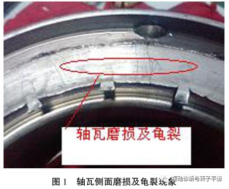
Stop the pump to uncover the tile check, found that the high pressure pump motor before the outer side of the shaft tile (by the high pressure pump side) is seriously worn, the outer circumferential surface of the gold colour blackened and off the tire phenomenon, the motor rotor block shoulder sticky melted gold (as shown in Figure 1). These phenomena confirm that the increasing temperature of the shaft tile is due to the motor rotor to the motor side of the direction of movement, resulting in the motor rotor shoulders and the outer side of the shaft tile eugene dynamic and static contact friction caused by. The specific causes of the axial thrust of the serious motor rotor movement are analysed as follows.
1.1 Mechanical centre does not coincide with the magnetic field centre
When the motor is in operation, its rotor will be located in the magnetic field centre, and there is a mechanical centre between the rotor spindle and the two bearings (i.e. the position of equal spacing between the shafts and bearings at both ends of the motor rotor). These 2 centres may be inconsistent. If the axial spacing of the axes is adjusted with the mechanical centre as a reference during installation, when the motor is started, the rotor will automatically be located at the centre of the magnetic field and the axial movement of the motor shaft will destroy the axial spacing adjusted during the original installation. When this deviation is not large, for gear type coupling, it can be compensated by the reserved axial clearance of the inner and outer gear sets; if the reserved axial clearance of the coupling is exceeded, the coupling and the driven shaft will be subjected to an axial applied force, resulting in end friction of the components and harmful effects such as heat generation.
1.2 Deviation of the rotating shaft system according to the coupling to find the centre
Shaft misalignment in the bearing deviation will add a large additional torque on the bearing, because the motor rotor can be in a certain range along the axial back and forth, the shaft system centre is not correct, the coupling will produce a fixed direction of axial force, so that the rotor in the role of axial force to overcome the magnetic field direction on one side of the drive, resulting in the motor rotor shoulder and bearing outside the Ugandan dynamic static friction. As shown in Figure 2.

1.3 Non-conformity of the lift at both ends of the motor rotor
Unreasonable journal lift at both ends of the motor rotor will cause the motor rotor to slide towards the end with less lift, overcoming the magnetic field force under the action of the axial force of its own gravity. Therefore, a reasonable degree of lift at both ends of the motor is the key to eliminating the axial force.
1.4 High-voltage motor shaft tile bearing positioning clearance design is too small
High pressure motor load end shaft shoulder positioning distance is 100.4mm, while the outer distance of the shaft tile is 100mm. that is to say, the motor rotor shaft shoulder to the shaft tile positioning play is only 0.2mm, for the high pressure pump high pressure high speed motor, the motor installation and magnetic centerline error amount is basically above 0.2mm, so 0.2mm play can not meet the high pressure motor high and low speed operation when the motor rotor runout. The amount of load end shaft shimmer is shown in Table 1.

1.5 High-voltage motor magnetic centreline position calibration and actual non-conformity
The original design magnetic centerline position of the motor is 178mm, while the measured value of the magnetic centerline when the motor is stationary under no-load condition is 176mm, and the position of the magnetic centerline after the motor is ramped up and after the free stop is 176mm, indicating that the original design of the motor has a certain deviation between the calibrated magnetic centerline position and the actual one.
1.6 High pressure pump internal vortex produces hydraulic disturbance force
High pressure pump in high speed and high flow operation, high pressure pump internal water vortex generated by the hydraulic disturbance force, will make the high pressure pump produce axial movement. However, from the connection and structure between the high-pressure pump, coupling and motor, it can be seen that the axial thrust of the high-pressure pump has a certain push force on the motor rotor, but it has little effect on the stability of the rotor.
2、Solution
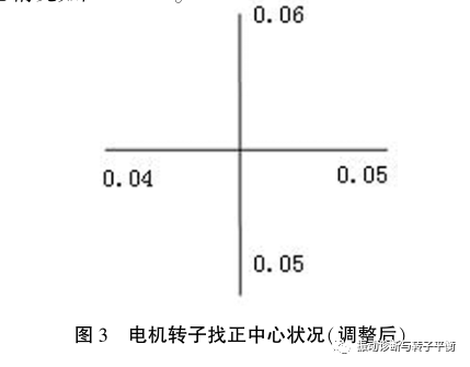
(1) According to the relevant data before adjustment, the shaft system centre and motor lift readjustment. When adjusting the rotor shaft system centre, focus on the motor rotor lifting situation, in the case of reasonable and consistent lifting at both ends of the coupler rotor and motor shaft centre, the motor rotor and high pressure pump centre respectively. After adjusting the shims of the bearing blocks at both ends of the motor, the centre situation is shown in Figure 3.
(2) Move the stator so that its ? The centre of force coincides with the rotor magnetic centre line and the amount of movement is basically equal to the amount of tampering after measurement. In engineering practice, when moving the stator, first remove the motor stator end cover and stator fixing bolts and locating pins, then use two jacks of suitable strength to move the stator end face at the same time, in order to monitor the amount of movement and top movement when the stator is tilted to move, but also in the direction of the stator movement and both sides of the smooth surface on the percentage table. According to the original design of this motor 178mm magnetic centerline position and the direction of motor rotor tampering, the motor stator to the high pressure pump direction to move 2, eliminate the original design and the actual error, so that the high pressure motor magnetic centerline position really reach 176mm.
(3) Machining the motor rotor in the bearing block, increasing the clearance on both sides of the shaft tile. Processing motor rotor bearing block shoulder, the motor rotor will be drawn out, the shaft extension end bearing block width size from 100.4mm processing to 110mm, so that, and the combination of the methods introduced earlier and after making appropriate adjustments? Motor operation can make both sides of the shaft tile to the shaft shoulder clearance of 5mm, increase the clearance on both sides of the shaft tile, to avoid the shaft shoulder and the side of the shaft tile dynamic and static friction failure. After the processing of the shaft shingle play as shown in Table 2.

In addition, can be analogous to the motor shaft extension end of the width of the shaft tile from the original 100mm to 90mm, so that the gap between the two sides of the shaft tile into 5.2mm, the same can also increase the clearance on both sides of the shaft tile, to achieve the desired purpose. But the shaft tile both sides of the pasteurized alloy thickness is generally 3mm, after turning 5mm will certainly be bearing both sides of the eugene surface completely cut off, this method is easy to cause the motor bearing temperature is too high phenomenon. Therefore, after the shaft tile turning must be re-poured pasteurized alloy and processing, time-consuming and laborious, and is not conducive to the maintenance of later equipment.
3、Conclusion
(1) for the use of gear-type coupling connected to the high pressure pump motor rotor, if the motor rotor axial movement phenomenon, should first consider the high pressure motor rotor ends of the Yang degree and shaft system centre problem.
(2) deal with high pressure motor rotor shaft shoulder and shaft tile bearing clearance problem, should be adjusted according to the motor speed and high pressure pump characteristics of the load end shaft tile clearance, to avoid causing the rotor shaft shoulder and bearing dynamic and static contact, touch grinding caused by the shaft tile temperature rise and issued by the impact of defects.
(3) through the above high-pressure pump motor rotor axial runout cause analysis, the high pressure pump high pressure motor in the plate for magnetic centre adjustment, rotor bearing block re-processing, and finally the shaft system to find the right, completely solve the high pressure pump motor rotor runout in the plate and the motor abnormal vibration, temperature rise problem, to avoid the motor due to sliding bearing damage caused by the motor sweeping the possible consequences of burning.